Author: Soma Electronics
This Is An Educational Website Of Soma Electronics.
How To Repair Digital Weight Scale In Bangladesh Walton Brand

tea2025b Amplifier Circuit Diagram PCB Layout
Temperature PID controller – Arduino
PID control
So now we know how to read the original temperature, let us control the heating element with this next planned mounted mountfat. I again mounted a routine circuit and uploaded the next code. This second code already has the PID algorithm created. We read the temperature, count the error, add the pid values, and create a PWM signal in the digital pin D3 that will be applied to MOSFET. I set the desired temperature at 100 degrees and use the LCD to print the set quality and real temperature.
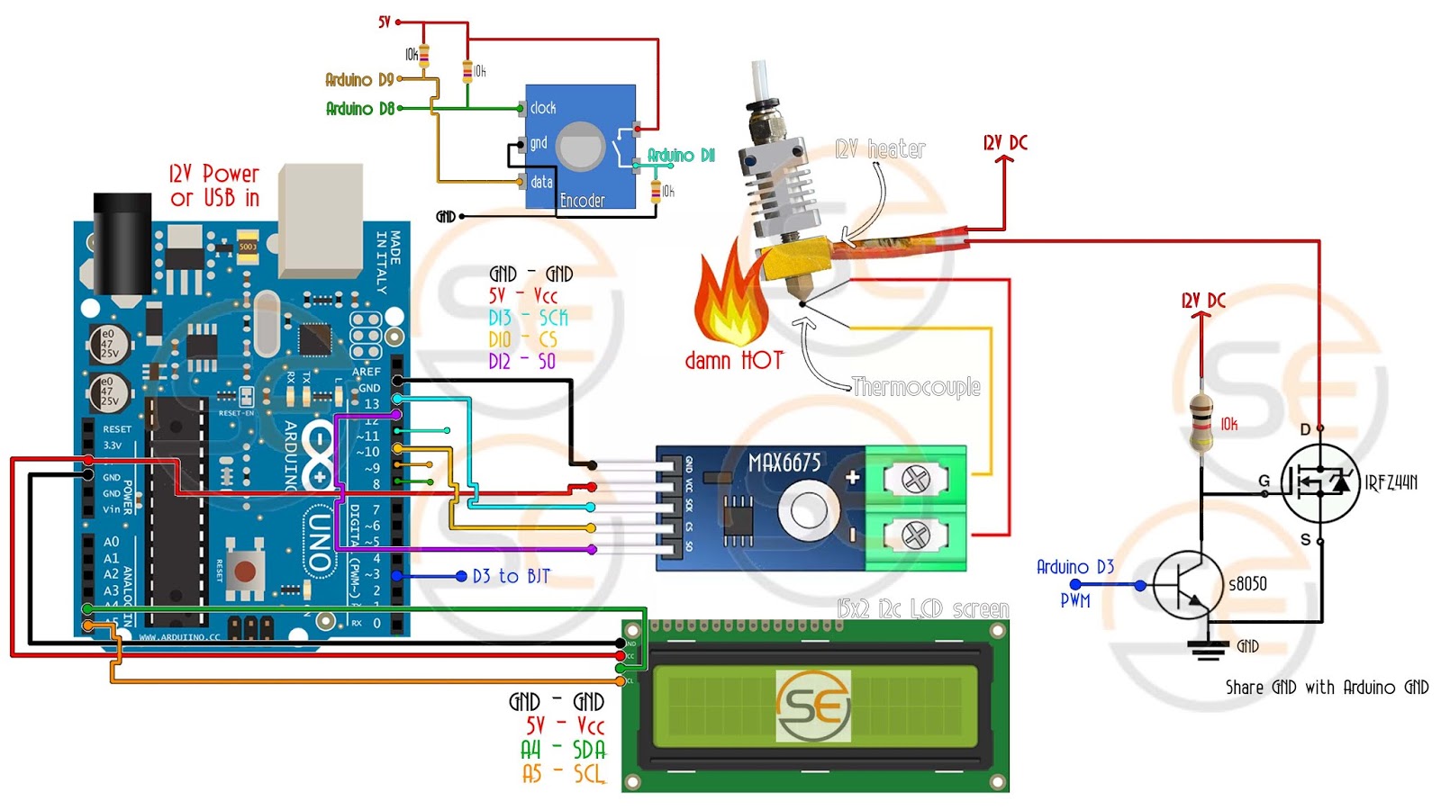
Code for specific PID control
Ok so the code below is a little bigger. But do not worry. It’s very easy. We set a variable set point at 100 degrees for this example. Then we read the actual temperature values of the temperatures as past examples. Then we use 3 constant and calculate PID sum. Depending on the quality, we make a PWM signal at pin D3 and apply it to a MOSFET gate using a BJT driver.
ARDUINO CODE
 |

You can see that the quality of the temperature is as having. But after many constant efforts of PID it and the tricky part of this project. So, try your own values to do what you need to do until you get the right. I suggest you start with 0 and equal to 0, and then gradually increase those values until you get good results.
Here I have the PWM signal of the MOSFET connected to my aceoloscope. 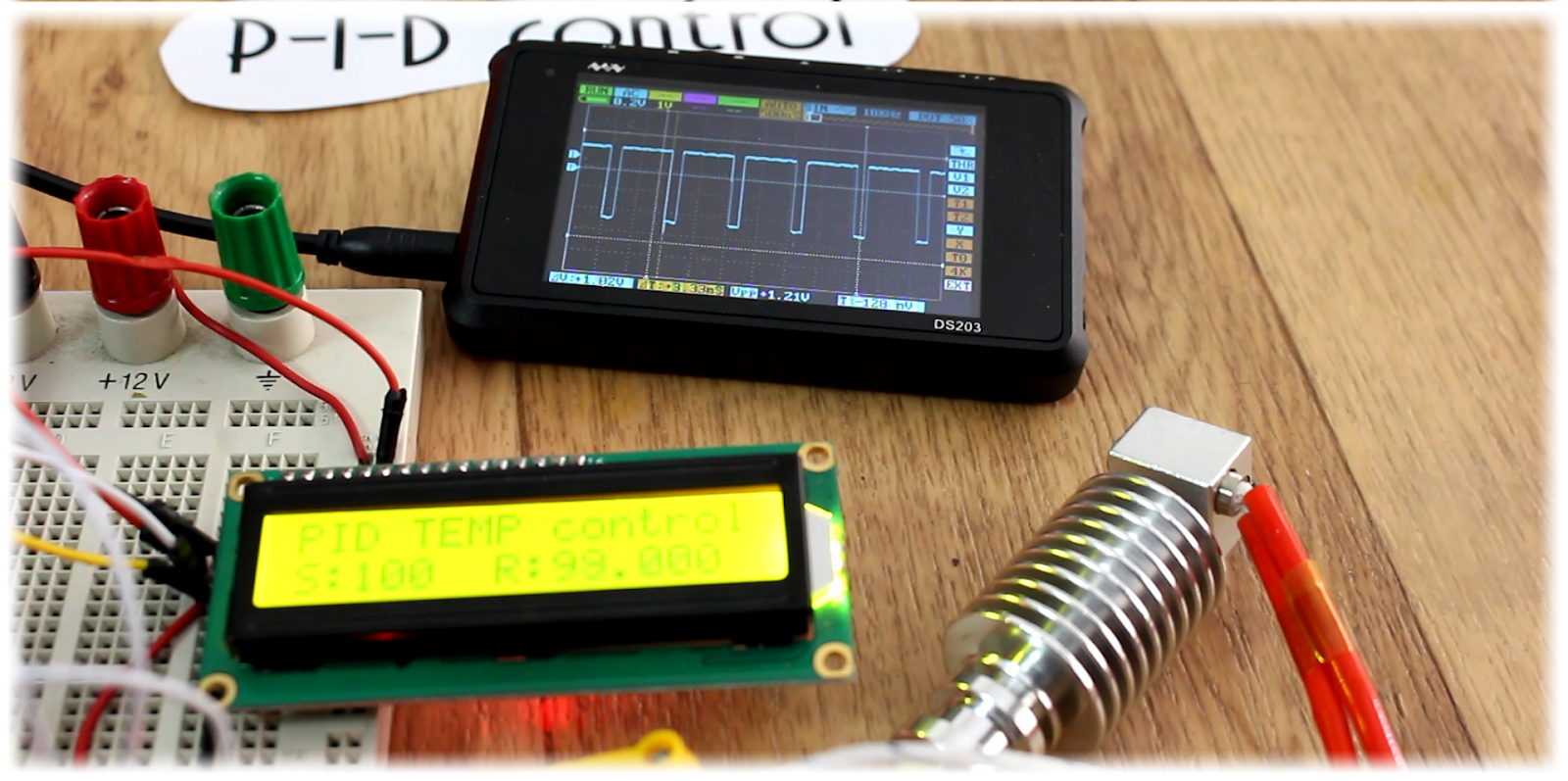 |
Initially, the system does not reach the desired value, because the pulse has a small width due to using the BJT to activate the N channel gate, so the mosque is activated with a lower quality in this field. Once it reaches the set quality it is used to maintain temperature and almost wambble begins. As you can see, if I try to cool the heating element by air in this air with the tube, the PWM signal width is low in keeping the same value. So, the control works.The default value is now 0 degrees. Press the Rotary Encoder Set button to enter or leave it to the left to decrease the temperature value. Again press the Set button and now you can set P constant for PID control. Press again and I select the value. Finally, press the button again and select D value. Now press the button and exit the menu and save the new settings. I put it at 100 degrees.
Pleter Module Air Cooling Soda Cooler Module TEC1 Lạnh Gì Mà Nhanh Thế
What Is Inside DC12V Solar Water Pump, How To Make At home
PIR Motion Sensor Home Security System Without Arduino
In This tutorial i will show how to make a anti theft security system and how to make this.
USB MP5 1080P Video Player For Old CRT TV And Monitor VGA S Video
In this tutorial i will show how to make a usb video player for Old CRT LED TV. You can make this video player for your old crt tv. now a days people are more upgraded for the reason compare with technology. Here is the video for making usb video decoder.
How To Make 4 Transistor Amplifier Using 35 0 35 Voltage Transformer
TTA5200 Amplifier Circuit Diagram
Today we can learn to build a single amplifier using transistors TTC5200. Usually we use TTC5200 and TTA1943. But in this circuit diagram, we can only see the TTA5200. We will need the center tap voltage. Center Tap Transformer for Transistor Amplifier. Conversion is an electrical power from one circuit other than a direct electrical connection. We have to use the transformer everywhere. But nowadays we can use the SMPS Circuit. Positive, Negative, and Ground Voltage We need this transformer to make amplifier. There is usually a transformer primary and second cable. For initial use we use AC 110v / 220 voltage. And we can get the output from seconds to what we need. Here are the secondary 2 wire outputs. But there is 3 cables for a center tube transmitter output voltage. For this circuit, we need to use a center tube transistor. Share this post if you like.
 |
|
#2sa5200 Amplifier Circuit PCD Layout
|
